Here we will try to get the basics of BluePill (STM32F103C8 processor) with STM32CubeIDE.
Requirements
- This article is based on STM32CubeIDE 1.3.1 that can be downloaded from STMicroelectronics web site (you will need too register for downloading this software).
- I'm using a "bluepill" device (64KB flash) from Aliexpress which is based on CKS F103C8 microcontroller (this is a chinese release of STM32F103C8 - CKS = China Key System Co., Ltd - note: this board has not the R10 issue).
- For programming the bluepill device from STM32CubeIDE, a STLINK device is required. I'm using STLINK V2, also from Aliexpress. This STLINK has been updated to V2J36S7 firmware (based on STMicroelectronics utilities)

The CKS F103C8 microcontroller
Hardware configuration
So, first step is to start STMCubeIDE and to create a new STM32 project (Menu : File -> New -> STM32 Project). STMCube will help us to configure the hardware.
As STMCubeIDE is mainly provided for programming STMicroelectronics own boards, the "bluepill" cannot be found in the "Board Selector". We will use the bluepill as a "generic board", and we have to select the STM32F103C8T6 device MCU from the "MCU/MPU Selector".

When the MCU is selected, pushing the "Next" Button will lead you to some project options. Keep the default, and "Finish".


Validate the associated perspective.

The STM32CubeMX perspective let us configure the features that will be used in our project.

Let's select the system core "SYS" component : "Debug" is set to "Serial Wire" (default is "No Debug"), and Timebase Source can be set to TIM4 (the 4th timer - you may choose any other unused timer).


Then, we will configure the GPIO connected to the onboard LED. On the MCU picture, click on the PC13 pin (on the top left) and set it to GPIO_Output. In the "GPIO Mode and Configuration" pane / "GPIO Pane", we can set the GPIO mode to "Output Open Drain" (may not be mandatory, LED should also work if the default push-pull is kept). Maximum output frequency may be kept to "LOW", and GPIO pull-up/pull-down resistors has to be kept to "No"

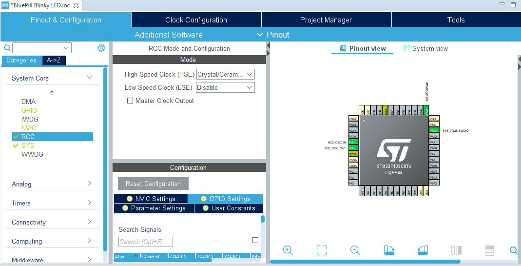
Now, still from the "System Core" pane, go to the RCC (Reset and Clock Controller) configuration, and set the "High Speed Clock (HSE)" to "Crystal/Ceramic" (default is "Disable").
So, we can go to the "Clock Configuration" pane. For clock configuration, you can use the resolver, however don't fully rely on the results, else the core may run at 48MHz (instead of the expected 72MHz).
Here are some details :
- "System Clock Mux" has to be set to PLLCLK
- HSE Crystal is 8MHz (nothing to change)
- The PLL (the "light blue" box) has a default x8 factor. The "PLLMul" has to be set "x9"
- Here USB is not used, so don't care... Else, just set the USB prescaler to "/1.5"
- APB1 Prescaler should be "/2", so PCLK1 is 36MHz. APB1 Timer clock shpidm be set to 72MHz by using the "x 2" mutiplier.

When Pinout and Clock configurations are done, just save the ".ioc" file, and STM32CubeIDE will generate the C code.
Blinking LED code
Now, let's have a look to the generated code. From the "outline" pane, select the MX_GPIO_Init function:
static void MX_GPIO_Init(void)
{
GPIO_InitTypeDef GPIO_InitStruct = {0};
/* GPIO Ports Clock Enable */ __HAL_RCC_GPIOC_CLK_ENABLE(); __HAL_RCC_GPIOD_CLK_ENABLE(); __HAL_RCC_GPIOA_CLK_ENABLE();
/*Configure GPIO pin Output Level */ HAL_GPIO_WritePin(GPIOC, GPIO_PIN_13, GPIO_PIN_RESET);
/*Configure GPIO pin : PC13 */ GPIO_InitStruct.Pin = GPIO_PIN_13; GPIO_InitStruct.Mode = GPIO_MODE_OUTPUT_OD; GPIO_InitStruct.Pull = GPIO_NOPULL; GPIO_InitStruct.Speed = GPIO_SPEED_FREQ_LOW; HAL_GPIO_Init(GPIOC, &GPIO_InitStruct);
}
We can see this function is initializing the GPIO devices, and GPIO C pin 13 is set as output (according the configuration done with the wizard).
Then, select the main function and look for the while(1) loop. Here we will insert the part of code in charge of the LED blinking :
/* USER CODE BEGIN WHILE */ while (1) { /* USER CODE END WHILE */ HAL_GPIO_TogglePin(GPIOC,GPIO_PIN_13); HAL_Delay(500);
/* USER CODE BEGIN 3 */ } /* USER CODE END 3 */
The loop is quite simple : first, we toggle GPIOC pin 13, then we wait for 500ms.An alternative is to set the LED off for ~0.9s, and light oit for ~0.1s :
while (1) { /* USER CODE END WHILE */
HAL_GPIO_WritePin(GPIOC,GPIO_PIN_13,SET); HAL_Delay(900); HAL_GPIO_WritePin(GPIOC,GPIO_PIN_13,RESET); HAL_Delay(100);
/* USER CODE BEGIN 3 */ } /* USER CODE END 3 */
(Note: As the LED is connected to the open drain, it is ON when the GPIO is low, and it is OFF when the GPIO is ON)
Building and running the project
We are now ready for building the project and uploading it into the bluepill board. We will also have to configure the "Run/Debug Settings". Clik on the "run", and you will got the "Edit launch configuration properties" interface. Switch to the "Debugger" tab :
- Debug Probe has to be set to "ST-LINK (OpenOCD)".
- Push the "Show generator options"
- Set the Connection to 4MHz (my VT-LINK is restricted to this speed
- Set the "Reset Mode" to "None"
- Press OK
Note: A .cfg (configuration) file has been generated into your project.
STM32CudeIDE is now building our project, and it will try to upload it. With bluepill based on CKS MCU, the upload will fail :
Open On-Chip Debugger 0.10.0+dev-01193-g5ce997d (2020-02-20-10:57)
Licensed under GNU GPL v2
For bug reports, read
http://openocd.org/doc/doxygen/bugs.html
none separate
Info : The selected transport took over low-level target control. The results might differ compared to plain JTAG/SWD
adapter speed: 8000 kHz
adapter_nsrst_delay: 100
Info : Listening on port 6666 for tcl connections
Info : Listening on port 4444 for telnet connections
Info : clock speed 8000 kHz
Info : STLINK V2J36S7 (API v2) VID:PID 0483:3748
Info : using stlink api v2
Info : Target voltage: 3.265600
Info : SRST line released
Warn : UNEXPECTED idcode: 0x2ba01477
Error: expected 1 of 1: 0x1ba01477
We need to declare the ID of the CKS MCU. We will declare this ID in the .cfg file. Before, we need to configure the debbugger for using this file,without any overwrite. From the Project Explorer, right-click on your project and select the "Properties" menu.

Edit the "Run/Debug settings" :

Go to the "debugger" tab, Edit the "Run/Debug settings" :

Set the "configuration script" to user defined" and choose the .cfg file. You can exit from this box, and edit the .cfg file. In the "BTCM CPU Variables" section, add the ID :
# This is an genericBoard board with a single STM32F103C8Tx chip## Generated by STM32CubeIDE# Take care that such file, as generated, may be overridden without any early notice. Please have a look to debug launch configuration setup(s)
source [find interface/stlink.cfg]
set WORKAREASIZE 0x5000
transport select "hla_swd"
set CHIPNAME STM32F103C8Tx
set BOARDNAME genericBoard
# Enable debug when in low power modes
# Enable debug when in low power modes
set ENABLE_LOW_POWER 1
# Stop Watchdog counters when halt
# Stop Watchdog counters when halt
set STOP_WATCHDOG 1
# STlink Debug clock frequency
# STlink Debug clock frequency
set CLOCK_FREQ 8000
# Reset configuration
# Reset configuration
# use software system reset if reset done
reset_config none
set CONNECT_UNDER_RESET 0
set CORE_RESET 0
# ACCESS PORT NUMBER
set AP_NUM 0
# GDB PORT
set GDB_PORT 3333
# BCTM CPU variables
# BCTM CPU variables
set CPUTAPID 0x2ba01477
source [find target/stm32f1x.cfg]
source [find target/stm32f1x.cfg]
Save the configuration, and push the "run" button again. Here the program can be applied to the board, and you can see the LED blinking according to the programmed duty cycle (10% or 90%).
Conclusion
We are able to develop a small "blinking LED" program for bluepill board, based on STM32CubeIDE. However, there's still a lot to do :
- How to use the debbuger
- How to use onboard devices (USB Serial, ...)
- ...
Aucun commentaire:
Enregistrer un commentaire
Remarque : Seul un membre de ce blog est autorisé à enregistrer un commentaire.